
CPU Design
Overview
This project explores the architectural tradeoffs between single-cycle , pipelined , cached , and multicore processor designs implemented on an FPGA. We designed, synthesized, and evaluated multiple processor variants to understand how pipelining, cache hierarchies, and parallelism affect clock frequency, instruction throughput, execution latency, and hardware resource utilization
Processor Architectures
5-Stage Pipelined Processor
The baseline design is a classic 5-stage pipeline consisting of Instruction Fetch (IF), Instruction Decode (ID), Execute (EX), Memory (MEM), and Write-Back (WB). A forwarding unit and hazard detection logic are used to resolve data and control hazards, enabling higher throughput by overlapping instruction execution.
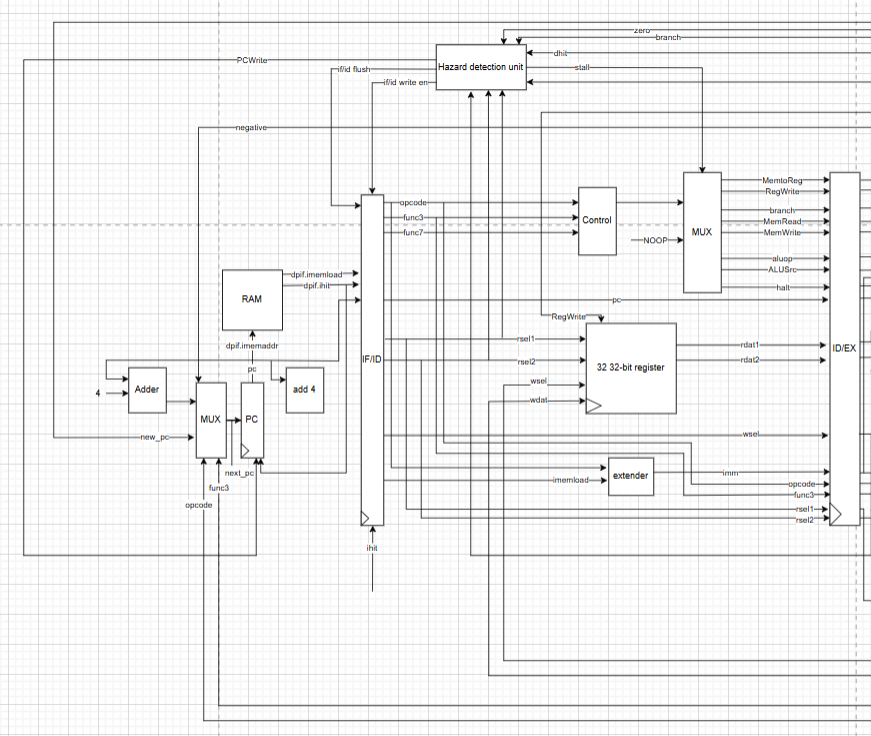 Figure 1. Instruction Fetch and Instruction Decode stages.
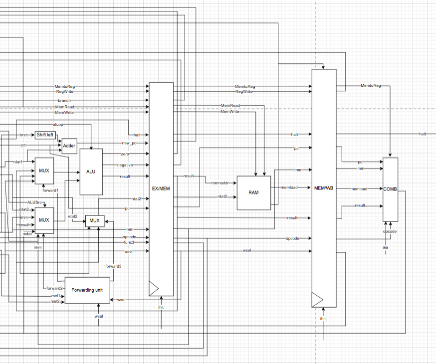 Figure 2. Execute, Memory, and Write-Back stages.
Pipeline with Cache Hierarchy
To reduce memory access latency, instruction and data caches were added to the pipeline. On cache hits, memory access latency is reduced to a single cycle, significantly improving CPI and total execution time for memory-intensive workloads.
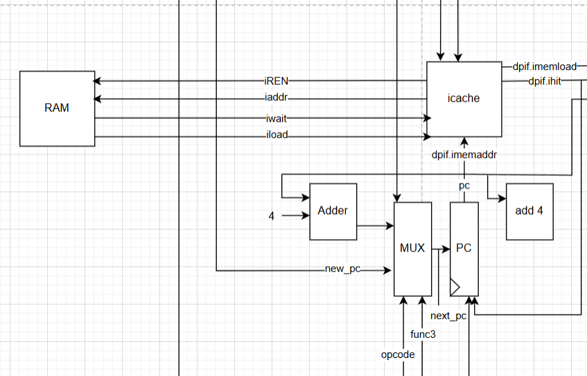 Figure 3. Instruction cache integration.
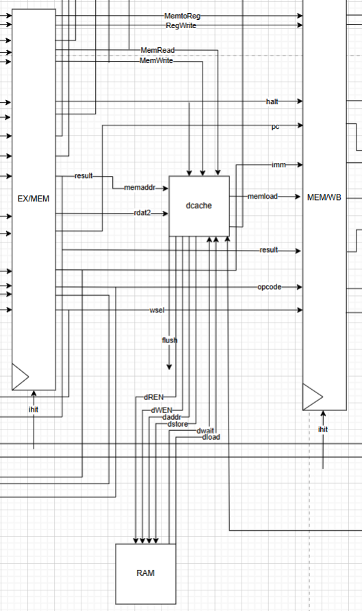 Figure 4. Data cache integration.
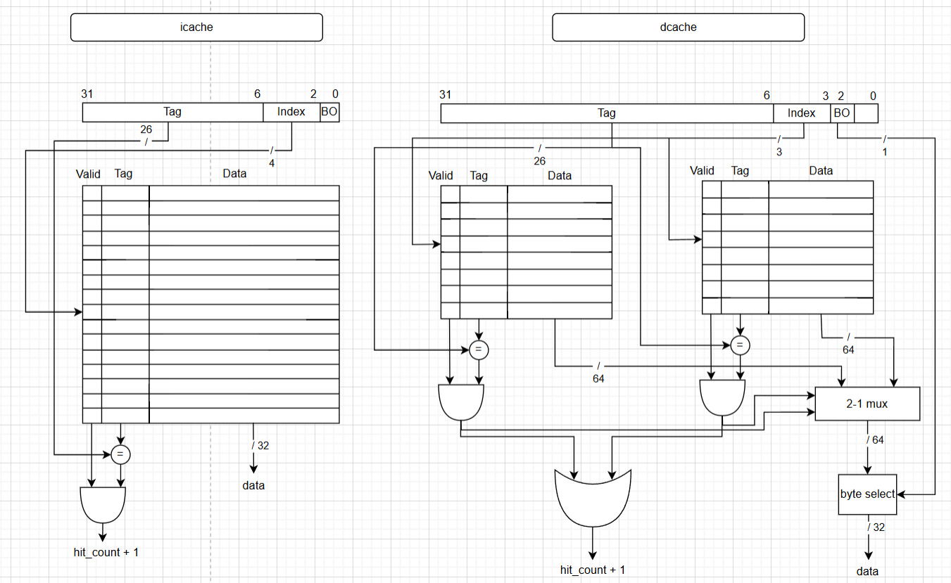 Figure 5. Instruction and data cache frame layout.
Multicore Processor Design
The multicore architecture consists of two identical processor cores sharing memory through a bus controller. Cache coherence is enforced using snooping and invalidation mechanisms to ensure correctness during concurrent memory accesses.
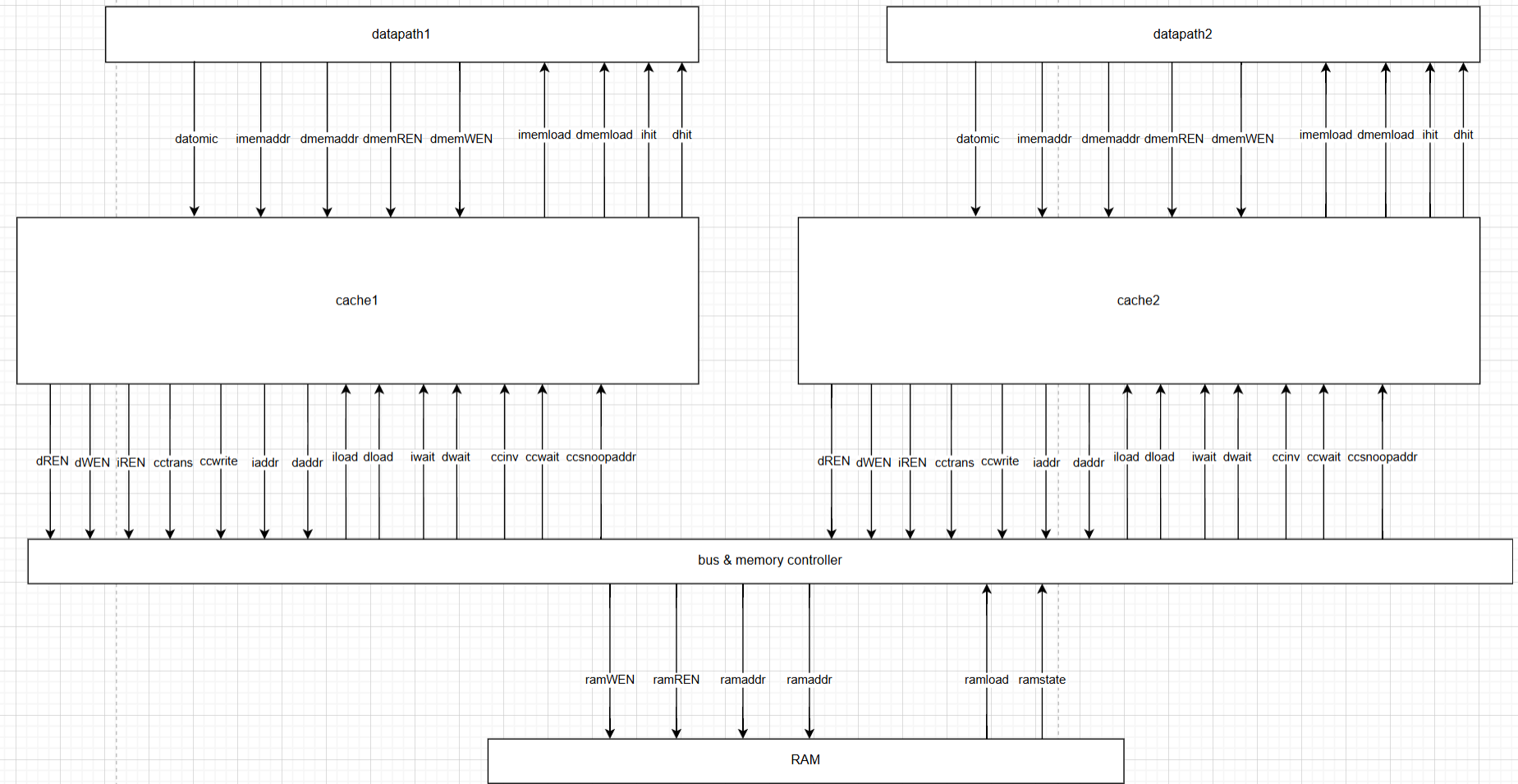 Figure 6. Dual-core processor architecture.
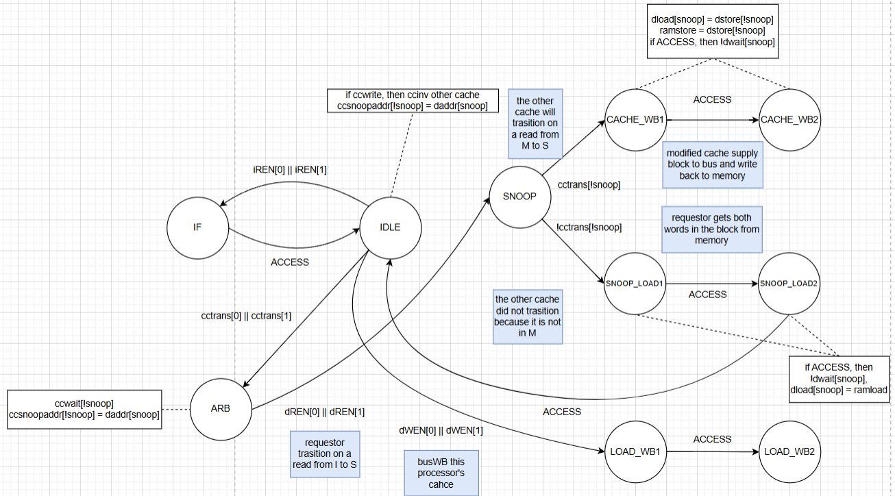 Figure 7. Bus controller state machine.
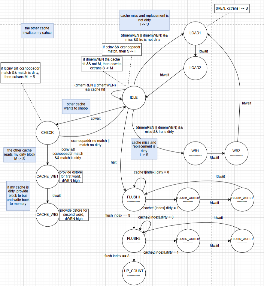 Figure 8. Data cache state machine.
Evaluation Methodology
Performance was measured using a mergesort benchmark compiled to assembly and executed under different memory latency settings. Metrics included:
- Maximum clock frequency (Fmax)
- Average clocks per instruction (CPI)
- Average instruction latency
- Total execution time
- FPGA resource usage (registers and logic elements)
Both single-threaded and dual-threaded workloads were evaluated for the multicore design
Results
Pipeline with Cache Performance
| Memory Latency | CPU Clock (MHz) | Executed Cycles | Avg CPI | Avg Latency / Instr (ns) | Total Exec Time (ns) |
|---|---|---|---|---|---|
| 0 cycles | 53.57 | 21,233 | 1.96 | 0.183 | 198.18 |
| 2 cycles | 59.30 | 23,273 | 2.15 | 0.181 | 196.23 |
| 6 cycles | 54.87 | 27,349 | 2.53 | 0.230 | 249.22 |
| 10 cycles | 59.58 | 31,425 | 2.90 | 0.244 | 263.72 |
Table 1. Performance metrics for the pipelined processor with cache.
Multicore Performance Highlights
- Dual-threaded multicore execution achieved up to 1.43× speedup over single-core designs.
- Single-threaded workloads performed worse on multicore due to synchronization overhead.
- Multicore designs are most effective when sufficient software parallelism exists.
Takeaways
- Caches provide increasing benefit as memory latency grows.
- Multicore architectures are most effective when software parallelism is available.
- Architectural enhancements must be evaluated holistically, considering both performance gains and hardware costs.
Contributions
- Pipeline, cache, and multicore implementation
- FPGA synthesis and performance evaluation
- Analysis of architectural tradeoffs across designs